Stealth
Objects invisible in the eyes of radars [1]
- Wave scattering: General problem position
- Numerical simulation of radar and general radar problems
- Absorbing and / or active treatment
- Effect of the shape of the object
- The geometrical optics and its limits
- Applications: F-117 Nighthawk and B-2 Spirit, stealth aircraft of the USAF
- Matlab scripts
Note:
The animations on this page come from some heavy and long computer calculations.
Patience thus while loading the page.
Wave scattering: General problem position
The general problem of propagation and scattering of waves basically occurs as follows: a source S (e.g. a radar) emits a wave; the wave propagates in space and is partially reflected on the obstacles present (here O1 and O2, blue and green).
The physical and mathematical models are designed for determining the amplitude of the resultant wave at any point in space, and therefore for example at a detector placed S. These models and their resolution depend on many parameters such as the type of waves, their wavelength, the geometry of the obstacles and their number, position, composition, ...
This is the so called direct problem: we know the source, barriers and physical parameters, and then seeks to determine the characteristics of the resulting wave in space. This problem has to be addressed and solved before tempting to solve the so called inverse problem (determining the position and the nature of the obstacles knowing the transmitted wave and resulting wave: this concern for example imaging and ultrasound problems), or other more specific variants such as the control of the radar echo of an object (or stealth: knowing the transmitted wave from the radar, what form and what material should we give to our object that will cause minimal disruption to waves emitted by the radar).
The physical and mathematical equations that govern the behavior of different types of waves have been known for a relatively long time.
For example, the behavior of electromagnetic waves (such as visible light, ultraviolet, X-rays and gamma rays, or radio waves used for transmitting the radio communications or all wireless communication such as used by cell phones) are known since about a century and a half, about 1870, when the Scottish James Clerck Maxwell has established their physical and mathematical laws.
These equations are well known, certainly, and for a long time, but still is it necessary to be able to solve them.
This is a complicated problem that one knows in theory and explicitly only in very particular cases. In other cases we numerically and computationally look for approximate values of our solution.
One of the goals of mathematics in this case study is then precisely to ensure that the calculated numerical values are close to the actual values.
Numerical simulation of radar and radar problems
Figure 2 shows an example of simulation
corresponding to the position schematically in Figure 1 above.
The simulation, as well as all the followings, is derived from digital calculations using the method of finite differences, described on this page.
A source, located in the bottom left corner, emits a wave for while in the space in which there are two objects.
Both objects perturb the propagation of the wave, and return a part to the source.
The curve below tracks at each instant the value of the field amplitude at the source:
By observing these results, several issues may arise, and several types of problems can be identified: From the measurement of the echo,
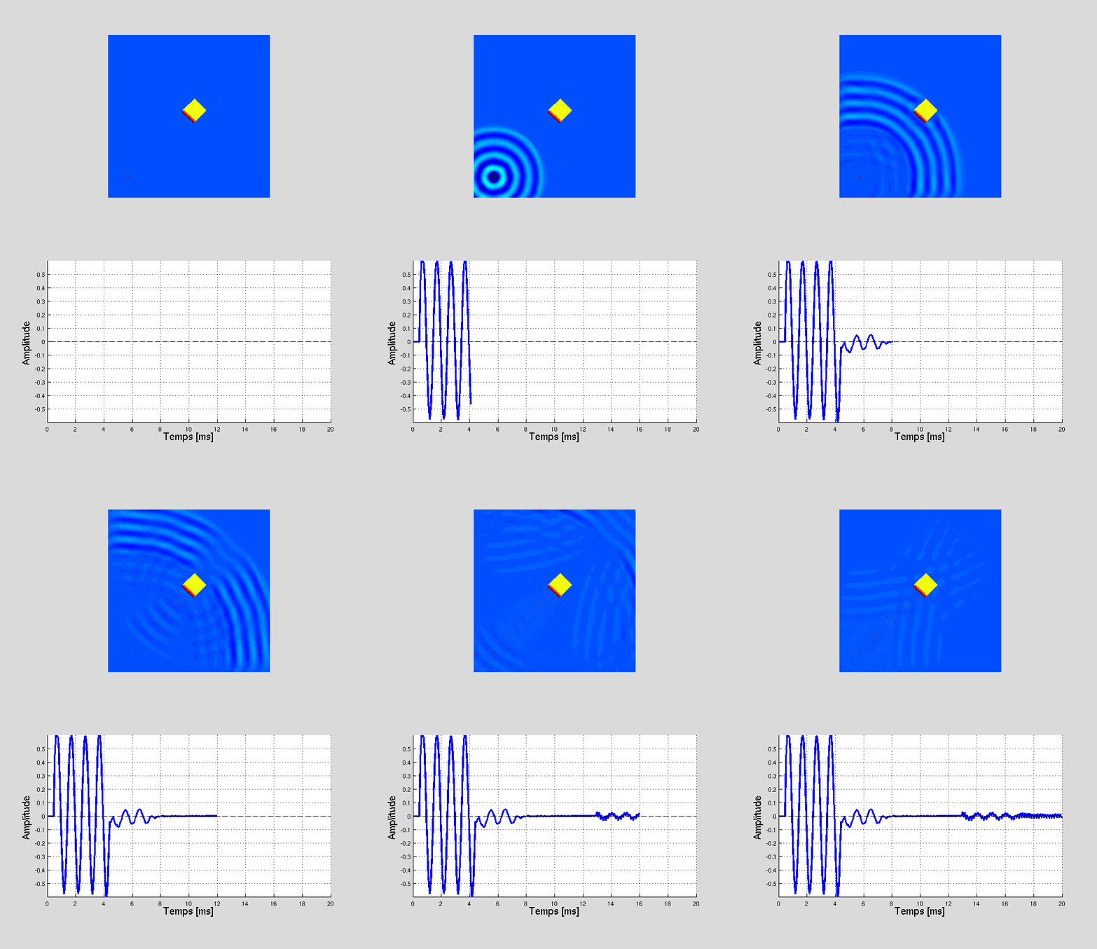
If a single object is present in front of the radar, as in Figure 3 below, one can effectively determine the distance to the radar, knowing the speed of wave propagation (for electromagnetic waves, the speed of light, 300 000 km / s) and the time taken by the waves to a radar / object return.
A source, located in the bottom left corner, emits a wave for while in the space in which there are two objects.
Both objects perturb the propagation of the wave, and return a part to the source.
The curve below tracks at each instant the value of the field amplitude at the source:
- the first part is sinusoidal: it is the amplitude of the field emitted;
- Then the amplitude is almost zero: the source stops transmitting, and echo on the target has not yet had time to reach it;
- Finally, the echo caused by the obstacles is backward propagated to the source. The amplitude of the wave after a round trip, has greatly reduced but the presence of obstacles in space nevertheless appears quite clearly from these measurements.
By observing these results, several issues may arise, and several types of problems can be identified: From the measurement of the echo,
- Can we locate and count the number of objects present in front of the radar?
- Can we go back to more precise information on the nature of these objects, as their shape, their nature, their constituent materials, ...?
- Which means could we implement in order to significantly reduce the echoes of these objects, so as to make them "invisible" ?
If a single object is present in front of the radar, as in Figure 3 below, one can effectively determine the distance to the radar, knowing the speed of wave propagation (for electromagnetic waves, the speed of light, 300 000 km / s) and the time taken by the waves to a radar / object return.
More generally speaking, the first two problems are difficult issues and ask the question:
is the radar measurement a very characteristic of the target ?.
In other words, are two different objects necessarily producing different echoes ?
Actually, the information contained in the measured echo in only a single direction is not enough to characterize the target (that's also mathematically proven!).
Used in this way, a single radar has a binary operation: either the signal is almost zero and it is decided that there is nothing in the space in front of him, or a signal with significant amplitude is picked meaning that something is present, and in which case which can be used to determine the distance of this "something" from the radar.
We can actually reconstruct the whole shape of the object present in front of the radar echoes if these echoes are known in all directions around the object.
This is of course unthinkable for a plane for example (radars should be, to achieve this, among others also positionned in the air above the plane…), but is for example more interesting in medical imaging problems. In this case, sensors can actually be positionned all around the object (patient ...) to determine the shape and nature of a particular object.
The issue of object discrimination from the radar echo is closely linked to the contrary, stealth of the object. The stealth characteristic of an object concerning its discretion, or "invisibility" in front of the radar.
The cube of Figure 3 is for example far from being considered stealthy. Indeed, one cube face is perpendicular to the present direction of the radar, a maximum energy of the incident wave is diffracted directly to the radar (the orthogonal to the reflection face of the said object is specular, and constitute some ways one of the worst enemies for an object that is to be stealthy).
Absorbing and / or active treatment
An idea to reduce this echo is to try to absorb the incident wave. This can be done by adjusting the material on the object.
The results of a previous simulation of the cube of Figure 3 , on which was added an absorbent layer on the side in front of the source, are shown on figure 4 .
It is also conceivable to add an active treatment, that is to say a set of sensors (antennas) on the surface of the object detecting the amplitude and phase of the incident wave at each instant, then electronically providing an opposed signal (in opposite phase more precisely).
Thus the total wave re-emitted by the object which the sum of the incident wave from the radar and that emitted by the object is zero at each time : no echo reaches the radar.
Effect of the shape of the object
The cube of Figure 3 returns a large part of the energy of the incident wave in the reverse direction (i.e. directly to the radar) because of its face perpendicular to the incident direction.
To reduce this energy returned, we can just simply and logically think about changing the shape of the object.
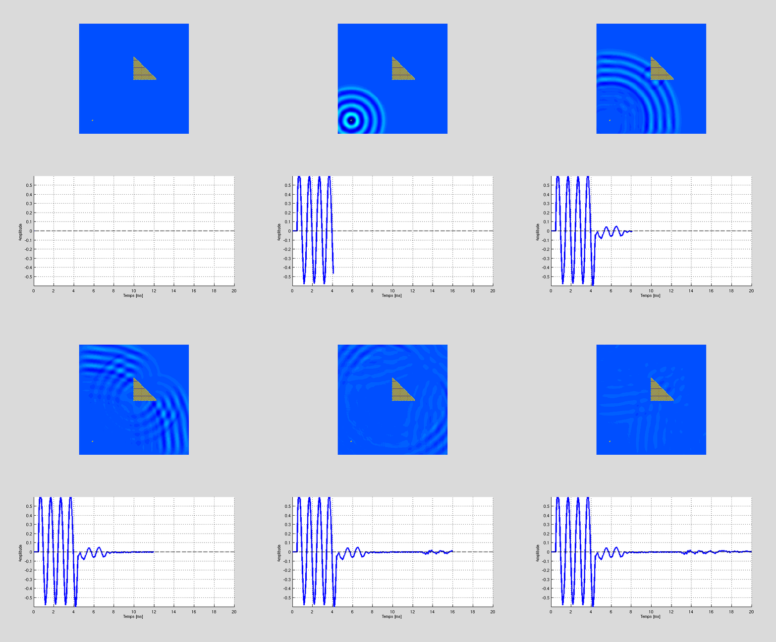
For example, the conical shape of the object on the Figure 5 scatters the incident wave from the radar in directions other than that of the radar precisely: the signal captured by the latter signal is in turn significantly reduced.
The geometrical optics and its limits
The above analysis, although quite simplistic, can significantly reduce the radar of an object.
This analysis is based on the representation of the paths of electromagnetic waves on the shelf, and so the laws of geometrical optics.
According to these laws, the waves propagate along straight paths. In both cases of the previous figure, in a square shape and a triangular shape, so there are the two types of trips given in the Figure 6.

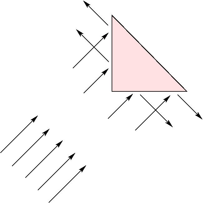
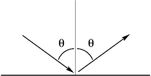
For the triangular object, the incident waves are reflected in directions other than the source: the radar is reduced (cf. simulation Figure 5 ).
The beam path follows the law of Snell of geometrical optics (right): the angle of incidence is the same as that of reflection.
The propagation of electromagnetic waves is described by Maxwell's equations. These equations are difficult to solve in most real cases. If geometrical optics offers an alternative to these equations, and simple tools for analyzing the behavior of these waves, it nevertheless does give an approximate solution. Indeed, with only geometrical optic in the simulation of Figure 5 , no wave would be reflected at all towards the source and the radar measurement would be exactly zero as shown schematically the path of rays of figure 6.
An electromagnetic wave is characterized by its frequency, or equivalently, by its wavelength.
The geometrical optics fails to account for the phenomena of scattering: when a wave interacts with one or more obstacles whose size is of the same order of magnitude as the wavelength, the wave behavior gives rise to phenomena interference (for example in Young's slit experiment, or diffraction by a small circular aperture).
It can be shown that the laws of geometrical optics are a first order approximation of Maxwell's equations when the wave frequency studied approaches infinity. This is the case for light waves, which have a very high frequency (of the order of 4.10 12 Hz for 12 Hz red until 7.10 for purple).On the other side, this hypothesis can clearly be impaired for the frequencies at which operate radars (of the order of GHz, or even of MHz).
In this case, it is necessary
- either to find more specific developments (second, third, ... order developments), as provides physical optics,
- or engage in the direct solution of Maxwell's equations. Examples of such a simulation are shown in figure 3, figure 4, figure 5.
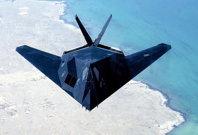
Applications: F-117 Nighthawk and the B-2 Spirit stealth aircraft of the USAF
|
The B-2 Spirit bomber, built by Northrop, based on the same principles as the F-117. Nevertheless, in more recent forms are most successful, and the "jagged" edges replaced by curves.
In addition, if the constraint stealth remained essential in its design, the progress of computer hardware and scientific knowledge (mathematics, physics and computer science) have improved markedly aerodynamics. |
|
Matlab scripts
 Matlab script for figure 2. - Simulation & animation: wave scattering from two bodies and Radar back signal received.
 Matlab script for figure 3. - Simulation & animation: wave scattering from a single body and Radar back signal received.
 Matlab script for figure 4. - Simulation & animation: Radar cross section reduction - Illustration of surface treatment
 Matlab script for figure 5. - Simulation & animation: illustration of shape effects on Radar cross section
[1] For more information: Décomposition en courants characteristiques. Application à l'analyse de SER. full text at this address, or this one. Back


